So, now on to creating the shape…
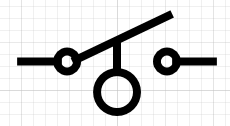
These is just some of the switches that the O.P. was talking about. They all have the same pattern, two contact points, a diagonal line indicating the connection and then a control symbol indicating how the switch is controlled/triggered.
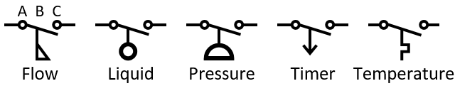
The shapes have three common points. A, the hinge connection, B, the symbol connection point and C, the contact point.
One thing I love about Visio is that the shapes are not clipart, the shapes can change based on the state of the shape. In this case, the shapes can be N.O. and N.C. (Normally Open and Normally Closed) and the difference in the shapes is the diagonal line touches above or below the contact point. Since this is Visio, the shapes can also show their current state, Open or Closed, the difference is whether the diagonal is touching the contact or there is a gap. Since there is no standard as to N.O. and N.C., the position can be above or below the contact point, I have simplified so that there are four positions. I will leave it up to theuser to identify theN.O. and N.C. positions.
While reviewing the existing shapes, (they do not all have the Normal or current setting), I noticed they were not consistent, some were single shapes and others were group shapes. Some of the shapes had a separate shape for the text block others have a separate block for the control symbol. It is possible to create a single shape, but for some, the shape needs a second text block. The first text block is for the shape label, but the Pressure switch could use a text block to represent the trigger pressure, the Time switch could use the trigger time.
The shape I will create will be a group shape, but most of the features will be in the group shape.
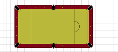
Caveat: Originally measurement values in Visio were absolute, then they introduced relative values, eventually they made relative the standard. So, a 1 in US units usually meant 1 inch, while in relative mode, the 1 wouldmean the full Height or Width. Absolute was useful when creating a shape that represents a real object. Like my Pool table.
Relative measurements were the actual measurements divided by the Height or Width, depending which was appropriate. So, the values were in the range of 0 to 1. Of course, the values can be negative or greater than one if the point was outside the bounding box. The relative shapesheet row types start with Rel. not all rows have a Rel version. The Ellipse does not, but EllipticalArcTo does. When changing RowType, Visio is nice enough to convert the cell values for that row. So, you need to know if the row is absolute or relative. The ellipses tripped me up a few times. With EllipticaArcTo, it was usually preceded with a RelMoveTo which contained the starting point, tripped me up a few times as well.
It is not uncommon for changes to a shape to also make changes to the bounding box, so in the Protection section of the Group shape I locked LockCalcWH. I also wanted the ability to stray outside the bounding box if I needed to.
Why would you want part of a shape outside the bounding box? I have a collection of unreleased Lego shapes and the pins are outside the bounding so they “disappear” when they are attached to other bricks. The pins are still there, they are just behind the other brick.
To start with, where should we keep the information that is used to control the look of the shape? The current shape uses the Scratch section for some things and Shape Data for others. If the information is exposed to the UI, then Shape Data should be used. For the things not exposed to the UI, I like using the User section because the items can be named. Far easier to understand than Scratch.A1. Of course, a Scratch row has more cells: X, Y, A, B, C and D. The User section is useful for isolating intershape references. If you Ungroup a shape, the group shape is deleted and the formulas using intershape references will be destroyed. It is far easier to reconnect an intershape reference in a User cell than trying to remember the formula that had the intershape reference and reconstitute it.
So, what is the difference between the User section and the Scratch section? Both are not directly visible from the UI, a User row can be referenced by name while a Scratch row is referenced by “Scratch.A3” (the A cell of the third Scratch row.). A User row has a value cell and a prompt, while a Scratch row has an X, Y, A, B, C and D cell. So, if you are dealing with a point, then the Scratch row makes sense. If not all the cells are used the lack of a name can be overcome by placing a name in an unused cell like D cell. (This is more useful to the developer rather than the user, because the name in the D cell is sort of documentation to reminder the developer the purpose of the row.)
Visio has had Data connectivity for decades, so, consideration for changing a shapes information has to be considered. There are several ways of changing shape information through the UI, but not all are available through automation, you need to use Shape Data.
Creating the shape…
So, the first step is to create the hinge/contact points. While doing the research I noticed that some shapes had alternate arrangements. Some had circles for the hinge/contact and others did not. For the sake of clarity, I will use the circles because without them, the switch is a straight line and I do not want to confuse any techies into thinking that the switch can be shorted out. The actual circles (Ellipses) are separate Geometry sections and, at a later date, the section’s NoShow cell can be set to hide the circle. Geometry sections 1 and 2 are the contact points A and C and Geometry section 3 is the lines that connect these points to the connection points of the shape.
The next part of the shape is the lever (Geometry 4), that makes contact between the hinge and the contact.

The lever is a line that pivots around the Hinge point, but rather than get into trig functions, I used a fixed horizontal distance and the choice of four vertical offsets. Though the trig functions would be more accurate, the difference in appearance is not enough to justify the complexity.
Now we can work on the different parts attached to the lever. These can be done as separate sub shapes, but since they are basically just a few lines, each can be their own Geometry section. The NoShow cell is used to determine which should appear.
For the Limit Switch (User.SwitchId = 1) …

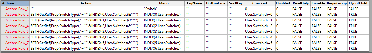
To give the user more control on which Geometry section is visible I added an Actions section.
So, it is possible to create the contact point, the hinge point and the lines to the connection points as a single Geometry section.
For the Liquid Switch (User.SwitchId=2)
As I showed in Visio Ellipse Part 3 an ellipse can be independent of a shapes’s Height and Width of an a Geometry section and just be defined by its’ center(X, Y) and the radii.

In addition to the Ellipse, The Pressure switch requires an elliptical arc (semi circle).
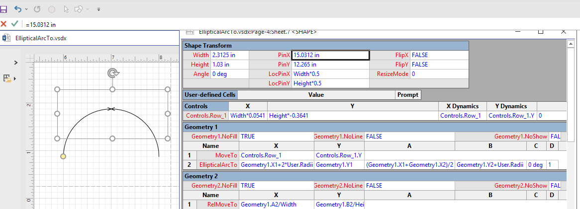
So, what are the required Geometry row cells? Since I want to go from left to right, I had to determine the right EllipticalArcTo values.

To figure it out, I created a circle and a straight line, centered them and then fragmented them. This resulted in two semicircular shapes. To make it obvious, I separated them vertically. I then duplicated the two shapes and positioned them above each other. After rotating the bottom pair, I joined the four shapes. I also changed the RelMoveTo rows to RelLineTo rows and reduced the Geometry sections to a RelMoveTo row and an EllipticalArcTo row.
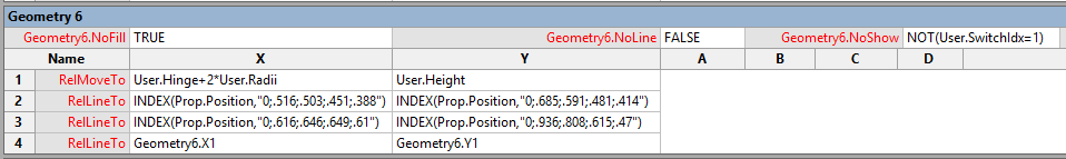
The Geo 1 and 2 arc up to the right, Geo 3 and 4 arc down to the left.
The Geo x labels match the Geometry sections in the shapesheet next to it.
Unfortunately, that did not help. My mistake was rotating the bottom shape, I should have flipped it. but… that only set the FlipX cell in the Shape Transform section. With some more playing I figured it out. After changing RelMoveTo to MoveTo, I just needed to swap the X,Y values in row 1 and 2. The A,B, C and D cells were unchanged. Setting the Width to 1 and the Height to 0.5 also helped in making it clear. Then it was just a matter of replacing A,B, C and D with references to the X,Y in the row and using the desired radii.
The blog Visio EllipticalArcTo explains the process.
The text processing is from the original shapes in the EE switches stencil. The shape is not perfect and has not been fully tested, but hopefully there is enough information here to embellish other shapes.
It can be downloaded from the download page.
John… Visio MVP in x-aisle
JohnVisioMVP.ca
