I have been working on a twisted pair Line Pattern for wires in Visio and I ran into a problem. I wanted to highlight the wires by adding an ouline to it but as it stretched the Fill patterns, there appeared vertical lines every time the pattern repeated.
(The horizontal lines in the below image are because the line was selected.)
It basically looked like the wires were cut.

the Line Pattern shape is made up of three sub shapes, a Red wire, a Blue wire and the outline. Initially I had tried setting the Blue and Red wire to have NoLine = False, but that caused the vertical lines on all sides of the shape. I tried to eliminate the end vertical lines by making a seperate outline shape with NoFill = True and NoLine = False and no vertical components.. The Red and Blue Lines were set to NoLine = True.
So, I made two copies of the Line Pattern, one just had the outline pattern and the other had the Red and Blue wires. So, it was obvious the problem was with the outline, there were no breaks in the Red and Blue wires.
So, I tried a line pattern, a simple pair of LineTos. This did not have a problem.

It turns out that I was closing off the Wire shapes with a MoveTo. Even though it did not show up in the Pattern, it did show up when stretched. Once I eliminated the need for a MoveTo, the problem was solved. This is the result with 2pt and 10 pt wieghts.

Even though you can use as many colours as you want, Visio only allows the user to change, only one colour from the UI. Setting the Line Colours, changes whatever is coloured black in the shape to take on that colour. If you want black in the shape you need to use almost black, something like RGB(0,1,00).
So, I created a series of Line Pattern with a fixed colour for one wire and the user could chose a Line Colour for the other wire.
This is a sampling of some of the Line Patterns and a variety of Line Colours.

So, what was the issue? As an experiment I tried a simple test. Do a Zorro with three lines. LineTo, MoveTo and anotherLineTo (none vertical). In a Visio drawing, that shows up as two seperate lines. In the Line Pattern editor, the same thing.
but rendered as a stretched Line Pattern?
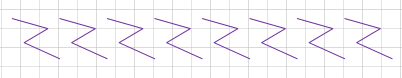
The mark of Zorro! So, if you are creating a Line Pattern, avoid MoveTo. I checked and RelMoveTo has the same issue.
I have uploaded the latest version (Jan 2021) to the Download page.
John… Visio MVP in x-aisle
JohnVisioMVP.ca

This is very impressive. I am struggling to even get a dash dot line to work. What is the magic? One thing I noticed is that if I ungroup a shape and group it again, I wind up with something different. It seems to “size” of the shape is smaller than the actual size. Any hits?
When you create a group shape, Visio creates a new shape with the component shapes as “sub”shapes. When you ungroup, this new shape is deleted. Most of the time this is not an issue, but if the designer decided to embellish this new shapes with features, those features are lost when ungrouped. You will have to explore the “top” shape of a group to determine the embellishments (new User, Shape Data, Connection Points or formulas in the cells.)
Ungrouping may affect the bounding box of the shape. With Line Patterns, you usually want a smaller bounding box. Ungrouping may have removed the protection on the size of the bounding box. Regrouping would use the unprotected size of the shapes.