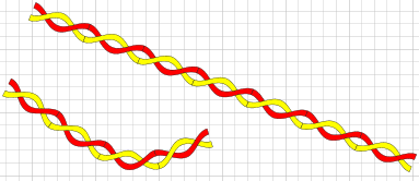
Recently, fellow Visio MVP Scott Helmers asked me if I had a line pattern that represented twisted pair wires. I mentioned that there was one in the collection of line patterns John GoldSmith talked about in 2008. Unfortunately, the example was a loose pair, so I decided to create my own.


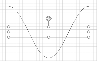
If you look at the twisted pair, they appear to be sinusoidal, specifically cosines. Since they are wires, it is a good guess that they are a pair of parallel cosine waves.
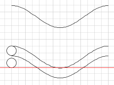
To make sure there is seperation, the bottom of the lower wire should be above the high point of the higher wire at some point, (the red line). Of course, this is an approximation and curves can be closer. This was just to work out the process rather than be as tight as possible,

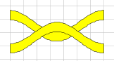
Once the distance between the two cosine waves was determined, there had to be a little manipulation to create a 2d shape from the two curves. Visio likes lines going around a shape in the same direction, So the lower line is flipped horizontally so that the curves are in opposite directions and a vertical lines are added in the same direction of rotation at either end (with no gaps.) The four shapes are Operation->Join and Operation->Fragment and then filled.
So, once you have a wire shape, duplicate it, invert it and align center and middle.
For reference one of the wires should be coloured red. The dots are just a reference to the wire size.

Selecting the two wires, do a fragment and recolour the segments. Select the same colour adjacent segments and Operation -> Union them.

Select the yellow wires segments and do an Operation-> Join and do the same for the reds.

You should now have something ready for a custom line pattern. One minor point is that the bounding box should be smaller. So, create a rectangle the length of the line segment and reduce the hight. Select the rectangle and set CalcHW to protected.

Change the rectangle to a group, Align the two wires with the rectangle and add them to the group. Edit the rectangle shape and delete the geometry for the rectangle.
To create the line pattern, Open the Document explorer and right click the Line Patterns folder and chose New Pattern…
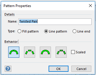
Name it. Chose Line Pattern as type and select the first behaviour.
The line pattern is in the Download page.
Eyeliner
I wanted the line pattern to standout by having an outline, but it appears that if you use Line/NoLine, you end up with a line between the segments as the pattern grows, giving the appearance that the wire is cut. I did try masking the problem by placing a NoLine rectangle of colour over top, but it did not always work. So, rather than hide the line I went with NoLine on all the component shapes and added an extra shape that only had the desired lines, sort of like using eye liner. In the download is three line patterns for twisted pair the first is without the outline, the second shows the issue with the “cut” wires and the third is the final version.
Living under the wrong sine
The original shape was based on a line pattern for sinusoidal shapes. Unfortunately, it had a smaller bounding box, so trying to align the component shapes was tricky. Moving the shape meant moving the bounding box and a small movement meant a large movement by the shape. The actual location of the bounding box was different than the shape so aliging was tricky.
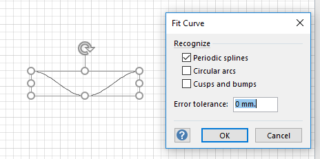
So, I did a Operation -> Fragment and converted the 1d shape to a 2d shape and that solved the aligment issues.
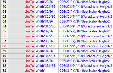
Another issue was that the Cosine shape was made of about 70 LineTo rows and I considered changing it to a NURB which would have curves rather than a series of straight lines, but that may be a bit of work converting that many rows, even with some VBA help.

So, I took a break and decided to look at customizing the ribbon, just to see what commands there were. Look what I found in the “F..”s.

by selecting the line with the collection of LineTos I was able to convert the 2d Cosine curve into a single row NURBSTo. Far easier than manually converting the shape.

… yes. that E cell is a lot longer than shown, but it is one cell rather than many rows.
Conclusion
Thank you Scott for the inspiration and John for the reference material.
… and Graham for the almost black technique.
So David, is that enough pictures? 😉
John… Visio MVP in x-aisle
JohnVisioMVP.ca