
Not all Visio shapes are pretty when they wander away from normal standards or have unnecessary embellishments, the shapes become ugly. With Visio shapes, even the shapes can be internally beautiful. Unnecessary code is ugly because it is distracting
Electrical engineering shapes
The Electrical engineering shapes were redone.
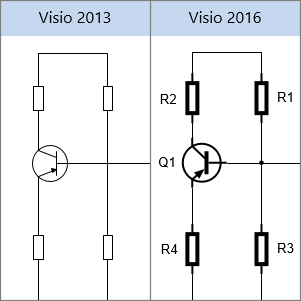
I was interested in electronics in high school and my degree was in Electrical Engineering. I was disappointed with Visio when they decided to revamp the Electrical Engineering shapes. The original shapes followed the industry standards, but the new ones had issues. The bold lines were distracting. Though discrete components like resistors, capacitors and transistors had leads for connectivity, these leads do not show on a schematic, so there is no need for the short bold lines where the components connect.
The standard symbol for a resistor is a zig zag line, in the stencil, resistors were just a rectangular block. (This was also a problem with the earlier version.)
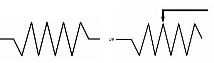
The first is a standard resistor and the second is a variable resistor. This makes more sense than a simple rectangular shape.
Diagonal Parking
A lot of the summer/part time work I had as I grew up was with a civil engineering firm. One of the fun projects, I was given was designing several playgrounds for a city. Some of them included parking. So, when I saw a question in Answers about diagonal parking in Visio, I thought it would be an easy answer. The OP wanted to change the direction of the stalls.
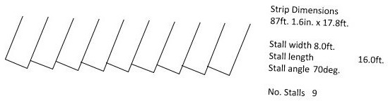
Simple answer, just flip the shape, but when he did, he got.
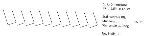
Something was severally wrong with the shape. When I checked out my version of the shape, I came up with a different shape that looked like one of these depending on a setting on the shape for background.

The shape had also been beautified. NOT! Delving into the shape also exposed more internal ugliness. Yes, how the shape is coded can be ugly. Even the Visio team has contributed to the ugliness. User and Shape Data sections grow and evolve as the shape is created, but there is no way to insert new rows or sort the sections. You can add a Shape Data sort key for the user’s benefit, but not the developer. ;-(
I get around this limitation by using VBA to create the shapes. It is very easy to insert or move around lines of VBA code to keep things sorted.
After decades of driving, I have come to realize most drivers flunked crayoning in kindergarten. They have an inability to remain between the lines. Though the lines are parallel, the end line is a diagonal. That would totally confuse them.
Engineers love standards and there is no way, this was a standard. It should have been something like.

Number of Stalls
The next thing I noticed was how the number of stalls was determined. The shape was horizontally stretched exposing preexisting stalls. Since the stretching would set the width to include partial slots, only full slots were made visible. The shape also had a right click command to trim the width.
I was happy to see that the shape was not a group shape, but a series of geometry sections. Simpler is cleaner.
Backgrounds
It appears that the reason for using two Geometry sections per stall was to add an object to represent having the stall painted rather than outlined by lines. This can be done using a single Geometry section and playing with the line size and NoFill cells. That is a lot of unnecessary extra code.
Simplifying the Sections
The shape had a predefined limit of fifteen stalls, but the shape had 31 Geometry sections. So each stall was made from at least two Geometry sections. The secondary section had checks to make sure if the primary section was a NoShow so did the secondary. (more unnecessary code).
Text
Rather than use the standard Visio text handling sections, the shape used User cells

Visio has some built in text handling features.
If the cell formula is a bit big for editing, you can use the Edit Formula button on the Editing section tab on the Shape Design tab.

or the fx button at the right side of the edit window.

This will bring up an Edit Formula Dialog. You can then add carriage returns after the “&”s to make the formula more readable. These will be lost when the dialog is closed, but while editing the text will be more readable.

The New Shape
For the revised shape, I only needed a simple opened ended rectangle, a single Geometry section.

The Geometry section would only need four rows for the four corners (1->4) and a fifth to return to the first corner (5) to close the shape.
So, the Geometry section is reasonably straight forward. They are basically the same, except each Geometry section after the first has an X Offset. It would be nice if there was a way in Visio to get the ordinal number of the Geometry Section.

The Shape Data is pretty much what was in the original shape. Prop.SCount was added so the user can specify the number of stalls (up to 20).
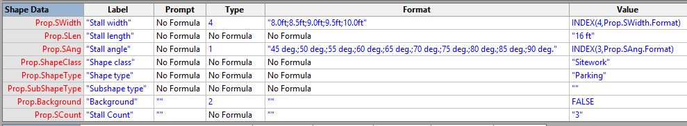
To make the shape work, the User-Defined cells
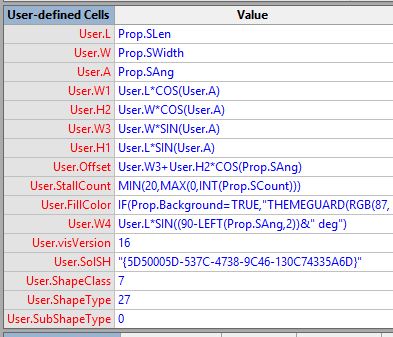
User.StripWidth was no longer needed because the right click command to reduce the shape width was removed. User.Strings, User.Text, User.Text1, User.Text2 and User.Text 3 were removed because I used Visio’s text handling.
It is interesting to note the last five User-Defined rows (User.visVersion -> User.SubShapeType) that were inherited from the original shape. It appears to be identifying cells that I have not noticed in the documentation. It looks like I have more fodder for my Visio Shape Dictionary. User.VisVersion is obvious, but it would be nice if ShapeClass, ShapeType and SubShapeType were enumerated somewhere.
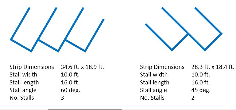
This is the result…
Mistakes
So, I did make a mistake with the math. Like the original shape I started with a basic shape set to 45 degrees. It was not until I adjusted the angle that I noticed my mistake. The problem was that Cos(45) = Sin(45), so on corner 3, I needed to switch from Cos() to Sin().
Creating the four corners was easy trig (the fifth corner was easier it just points to the first corner),, but I did get in trouble trying to work out the offset of the subsequent sections, it should have been easy, but I got in trouble by overthinking. The offset stated at the first corner 2 and went to somewhere to a location on a line between corner 3 and 4.
Rather than get more confused, I asked for help (DP, JG). Of course this request gave me the incentive to work it out before I got a response. The diagram had a lot of distracting lines, angles and measurements. So I went to an old school method, a red pen. I highlighted the lines and angles I needed to concentrate on and it became obvious. It was a simple right-angle .triangle with a known angle and vertical side. All that was needed was a simple Tan() function to work out the missing side.
You can find the shape and the shape it was based on on my Download Page (Parking Stall).
I hope you find this useful.
John… Visio MVP in x-aisle
JohnVisioMVP.ca
